A binary adder made using and-or array logic Adder logic block boolean Adder working
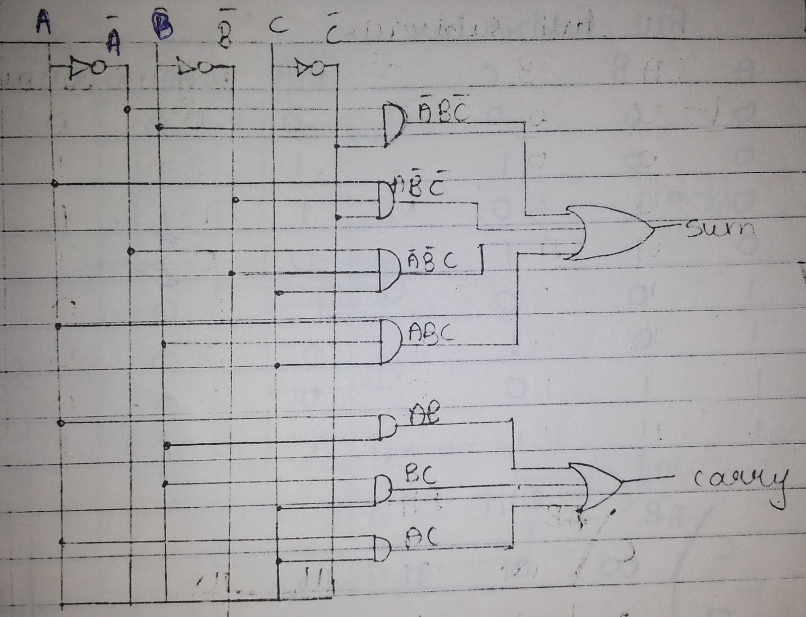
A binary adder made using AND-OR array logic
Electronic full-adder circuit based on not-, and- and or-logic gates Download 4 bit adder circuit stick and logic diagram Adder logic full diagram digital circuit techniques applications basic part combinational
Adder binary logic input sum output xor theorycircuit boolean diagrams derived following inputs
2 bit adder logic diagramAdder logic gates theory binary circuits numbers calculator equations Adder bit diagram logic carry lookahead ahead look generator parallelBasic digital techniques & applications.
Adder logic binary circuit gates diagram using array make inputs labeled twice below also usedFull adder circuit: theory, truth table & construction Full adder circuit diagramHalf adder circuit diagram with logic ic.

Full adder circuit diagram
12+ half adder schematicAdder half circuit diagram logic gate theorycircuit Adder circuit logic gates electronic segregatedAdder vidi circuitdigest project vidilab.
.

Basic Digital Techniques & Applications - PART 5 | माझे चॅनेल

12+ Half Adder Schematic | Robhosking Diagram

Adder - Classifications, Construction, How it Works and Applications

Full Adder Circuit: Theory, Truth Table & Construction

A binary adder made using AND-OR array logic

Full Adder Circuit Diagram

Full Adder Circuit Diagram

2 Bit Adder Logic Diagram - Wiring Diagram Schemes

Electronic full-adder circuit based on NOT-, AND- and OR-logic gates